White Paper on Monitors (CRT/ LCD/LED),Memory
COURTESY :- vrindawan.in
Wikipedia
A computer monitor is an output device that displays information in pictorial or textual form. A discrete monitor comprises a visual display, support electronics, power supply, housing, electrical connectors, and external user controls.

The display in modern monitors is typically an LCD with LED back light, having by the 2010s replaced CCFL back lit LCDs. Before the mid-2000s, most monitors used a CRT. Monitors are connected to the computer via Display Port, HDMI, USB-C, DVI, VGA, or other proprietary connectors and signals.
Originally, computer monitors were used for data processing while television sets were used for video. From the 1980s onward, computers (and their monitors) have been used for both data processing and video, while televisions have implemented some computer functionality. In the 2000s, the typical display aspect ratio of both televisions and computer monitors has changed from 4:3 to 16:9.
Modern computer monitors are mostly interchangeable with television sets and vice versa. As most computer monitors do not include integrated speakers, TV tuners, nor remote controls, external components such as a DTA box may be needed to use a computer monitor as a TV set.
Early electronic computer front panels were fitted with an array of light bulbs where the state of each particular bulb would indicate the on/off state of a particular register bit inside the computer. This allowed the engineers operating the computer to monitor the internal state of the machine, so this panel of lights came to be known as the ‘monitor’. As early monitors were only capable of displaying a very limited amount of information and were very transient, they were rarely considered for program output. Instead, a line printer was the primary output device, while the monitor was limited to keeping track of the program’s operation.
Computer monitors were formerly known as visual display units (VDU), particularly in British English. This term mostly fell out of use by the 1990s.
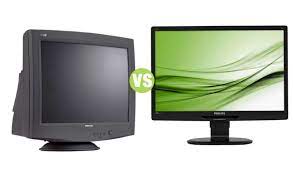
Multiple technologies have been used for computer monitors. Until the 21st century most used cathode-ray tubes but they have largely been superseded by LCD monitors.
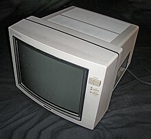
A cathode-ray tube (CRT) is a vacuum tube containing one or more electron guns, which emit electron beams that are manipulated to display images on a phosphorescent screen. The images may represent electrical wave forms (oscilloscope), pictures (television set, computer monitor), radar targets, or other phenomena. A CRT on a television set is commonly called a picture tube. CRTs have also been used as memory devices, in which case the screen is not intended to be visible to an observer. The term cathode ray was used to describe electron beams when they were first discovered, before it was understood that what was emitted from the cathode was a beam of electrons.
In CRT television sets and computer monitors, the entire front area of the tube is scanned repeatedly and systematically in a fixed pattern called a raster. In color devices, an image is produced by controlling the intensity of each of three electron beams, one for each additive primary color (red, green, and blue) with a video signal as a reference. In modern CRT monitors and televisions the beams are bent by magnetic deflection, using a deflection yoke. Electrostatic deflection is commonly used in oscilloscopes.

The rear of a 14-inch color cathode-ray tube showing its deflection coils and electron guns

Typical 1950s United States monochrome television set

Snapshot of a CRT television showing the line of light being drawn from left to right in a raster pattern

Animation of the image construction with interlacing method

Color computer monitor electron gun
A CRT is a glass envelope which is deep (i.e., long from front screen face to rear end), heavy, and fragile. The interior is evacuated to 0.01 pascals (1×10⁻⁷ atm) to 0.1 micro pascals (1×10⁻¹² atm) or less, to facilitate the free flight of electrons from the gun(s) to the tube’s face without scattering due to collisions with air molecules. As such, handling a CRT carries the risk of violent implosion that can hurl glass at great velocity. The face is typically made of thick lead glass or special barium-strontium glass to be shatter-resistant and to block most X-ray emissions. CRTs make up most of the weight of CRT TVs and computer monitors.
Since the early 2010s, CRTs have been superseded by flat-panel display technologies such as LCD, plasma display, and OLED displays which are cheaper to manufacture and run, as well as significantly lighter and less bulky. Flat-panel displays can also be made in very large sizes whereas 40 in (100 cm) to 45 in (110 cm) was about the largest size of a CRT.
A CRT works by electrically heating a tungsten coil which in turn heats a cathode in the rear of the CRT, causing it to emit electrons which are modulated and focused by electrodes. The electrons are steered by deflection coils or plates, and an anode accelerates them towards the phosphor-coated screen, which generates light when hit by the electrons.
Cathode rays were discovered by Julius Plücker and Johann Wilhelm Hittorf. Hittorf observed that some unknown rays were emitted from the cathode (negative electrode) which could cast shadows on the glowing wall of the tube, indicating the rays were traveling in straight lines. In 1890, Arthur Schuster demonstrated cathode rays could be deflected by electric fields, and William Crookes showed they could be deflected by magnetic fields. In 1897, J. J. Thomson succeeded in measuring the charge-mass-ratio of cathode rays, showing that they consisted of negatively charged particles smaller than atoms, the first “subatomic particles”, which had already been named electrons by Irish physicist George Johnstone Stoney in 1891. The earliest version of the CRT was known as the “Braun tube”, invented by the German physicist Ferdinand Braun in 1897. It was a cold-cathode diode, a modification of the Crookes tube with a phosphor-coated screen. Braun was the first to conceive the use of a CRT as a display device.
In 1908, Alan Archibald Campbell-Swinton, fellow of the Royal Society (UK), published a letter in the scientific journal Nature, in which he described how “distant electric vision” could be achieved by using a cathode-ray tube (or “Braun” tube) as both a transmitting and receiving device. He expanded on his vision in a speech given in London in 1911 and reported in and the Journal of the Röntgen Society.
The first cathode-ray tube to use a hot cathode was developed by John Bertrand Johnson (who gave his name to the term Johnson noise) and Harry Weiner Weinhart of Western Electric, and became a commercial product in 1922. The introduction of hot cathodes allowed for lower acceleration anode voltages and higher electron beam currents, since the anode now only accelerated the electrons emitted by the hot cathode, and no longer had to have a very high voltage to induce electron emission from the cold cathode.
In 1926, Kenjiro Takayanagi demonstrated a CRT television that received images with a 40-line resolution. By 1927, he improved the resolution to 100 lines, which was unrivaled until 1931. By 1928, he was the first to transmit human faces in half-tones on a CRT display. In 1927, Philo Farnsworth created a television prototype. The CRT was named in 1929 by inventor Vladimir K. Zworykin. RCA was granted a trademark for the term (for its cathode-ray tube) in 1932; it voluntarily released the term to the public domain in 1950.
In the 1930s, Allen B. DuMont made the first CRTs to last 1,000 hours of use, which was one of the factors that led to the widespread adoption of television.
The first commercially made electronic television sets with cathode-ray tubes were manufactured by Telefunken in Germany in 1934.
In 1947, the cathode-ray tube amusement device, the earliest known interactive electronic game as well as the first to incorporate a cathode-ray tube screen, was created.
From 1949 to the early 1960s, there was a shift from circular CRTs to rectangular CRTs, although the first rectangular CRTs were made in 1938 by Telefunken. While circular CRTs were the norm, European TV sets often blocked portions of the screen to make it appear somewhat rectangular while American sets often left the entire front of the CRT exposed or only blocked the upper and lower portions of the CRT.
In 1954, RCA produced some of the first color CRTs, the 15GP22 CRTs used in the CT-100, the first color TV set to be mass-produced. The first rectangular color CRTs were also made in 1954. However, the first rectangular color CRTs to be offered to the public were made in 1963. One of the challenges that had to be solved to produce the rectangular color CRT was convergence at the corners of the CRT. In 1965, brighter rare earth phosphors began replacing dimmer and cadmium-containing red and green phosphors. Eventually blue phosphors were replaced as well.
The size of CRTs increased over time, from 20 inches in 1938, to 21 inches in 1955, 35 inches by 1985, and 43 inches by 1989. However, experimental 31 inch CRTs were made as far back as 1938.
In 1960, the Aiken tube was invented. It was a CRT in a flat-panel display format with a single electron gun. Deflection was electrostatic and magnetic, but due to patent problems, it was never put into production. It was also envisioned as a head-up display in aircraft. By the time patent issues were solved, RCA had already invested heavily in conventional CRTs.
1968 marks the release of Sony Trinitron brand with the model KV-1310, which was based on Aperture Grille technology. It was acclaimed to have improved the output brightness. The Trinitron screen was identical with its upright cylindrical shape due to its unique triple cathode single gun construction.
A liquid-crystal display (LCD) is a flat-panel display or other electronically modulated optical device that uses the light-modulating properties of liquid crystals combined with polarizers. Liquid crystals do not emit light directly, instead using a backlight or reflector to produce images in color or monochrome. LCDs are available to display arbitrary images (as in a general-purpose computer display) or fixed images with low information content, which can be displayed or hidden. For instance: preset words, digits, and seven-segment displays, as in a digital clock, are all good examples of devices with these displays. They use the same basic technology, except that arbitrary images are made from a matrix of small pixels, while other displays have larger elements. LCDs can either be normally on (positive) or off (negative), depending on the polarizer arrangement. For example, a character positive LCD with a back light will have black lettering on a background that is the color of the back light, and a character negative LCD will have a black background with the letters being of the same color as the back light. Optical filters are added to white on blue LCDs to give them their characteristic appearance.

LCDs are used in a wide range of applications, including LCD televisions, computer monitors, instrument panels, aircraft cockpit displays, and indoor and outdoor signage. Small LCD screens are common in LCD projectors and portable consumer devices such as digital cameras, watches, digital clocks, calculators, and mobile telephones, including smartphones. LCD screens are also used on consumer electronics products such as DVD players, video game devices and clocks. LCD screens have replaced heavy, bulky cathode-ray tube (CRT) displays in nearly all applications. LCD screens are available in a wider range of screen sizes than CRT and plasma displays, with LCD screens available in sizes ranging from tiny digital watches to very large television receivers. LCDs are slowly being replaced by OLEDs, which can be easily made into different shapes, and have a lower response time, wider color gamut, virtually infinite color contrast and viewing angles, lower weight for a given display size and a slimmer profile (because OLEDs use a single glass or plastic panel whereas LCDs use two glass panels; the thickness of the panels increases with size but the increase is more noticeable on LCDs) and potentially lower power consumption (as the display is only “on” where needed and there is no backlight). OLEDs, however, are more expensive for a given display size due to the very expensive electroluminescent materials or phosphors that they use. Also due to the use of phosphors, OLEDs suffer from screen burn-in and there is currently no way to recycle OLED displays, whereas LCD panels can be recycled, although the technology required to recycle LCDs is not yet widespread. Attempts to maintain the competitiveness of LCDs are quantum dot displays, marketed as SUHD, QLED or Triluminos, which are displays with blue LED backlighting and a Quantum-dot enhancement film (QDEF) that converts part of the blue light into red and green, offering similar performance to an OLED display at a lower price, but the quantum dot layer that gives these displays their characteristics can not yet be recycled.
Since LCD screens do not use phosphors, they rarely suffer image burn-in when a static image is displayed on a screen for a long time, e.g., the table frame for an airline flight schedule on an indoor sign. LCDs are, however, susceptible to image persistence. The LCD screen is more energy-efficient and can be disposed of more safely than a CRT can. Its low electrical power consumption enables it to be used in battery-powered electronic equipment more efficiently than a CRT can be. By 2008, annual sales of televisions with LCD screens exceeded sales of CRT units worldwide, and the CRT became obsolete for most purposes.
Each pixel of an LCD typically consists of a layer of molecules aligned between two transparent electrodes, often made of Indium-Tin oxide (ITO) and two polarizing filters (parallel and perpendicular polarizers), the axes of transmission of which are (in most of the cases) perpendicular to each other. Without the liquid crystal between the polarizing filters, light passing through the first filter would be blocked by the second (crossed) polarizer. Before an electric field is applied, the orientation of the liquid-crystal molecules is determined by the alignment at the surfaces of electrodes. In a twisted nematic (TN) device, the surface alignment directions at the two electrodes are perpendicular to each other, and so the molecules arrange themselves in a helical structure, or twist. This induces the rotation of the polarization of the incident light, and the device appears gray. If the applied voltage is large enough, the liquid crystal molecules in the center of the layer are almost completely untwisted and the polarization of the incident light is not rotated as it passes through the liquid crystal layer. This light will then be mainly polarized perpendicular to the second filter, and thus be blocked and the pixel will appear black. By controlling the voltage applied across the liquid crystal layer in each pixel, light can be allowed to pass through in varying amounts thus constituting different levels of gray.
The chemical formula of the liquid crystals used in LCDs may vary. Formulas may be patented. An example is a mixture of 2-(4-alkoxyphenyl)-5-alkylpyrimidine with cyanobiphenyl, patented by Merck and Sharp Corporation. The patent that covered that specific mixture expired.
Most color LCD systems use the same technique, with color filters used to generate red, green, and blue subpixels. The LCD color filters are made with a photolithography process on large glass sheets that are later glued with other glass sheets containing a TFT array, spacers and liquid crystal, creating several color LCDs that are then cut from one another and laminated with polarizer sheets. Red, green, blue and black photoresists (resists) are used. All resists contain a finely ground powdered pigment, with particles being just 40 nanometers across. The black resist is the first to be applied; this will create a black grid (known in the industry as a black matrix) that will separate red, green and blue sub pixels from one another, increasing contrast ratios and preventing light from leaking from one sub pixel onto other surrounding sub pixels. After the black resist has been dried in an oven and exposed to UV light through a photo mask, the unexposed areas are washed away, creating a black grid. Then the same process is repeated with the remaining resists. This fills the holes in the black grid with their corresponding colored resists. Another color-generation method used in early color PDAs and some calculators was done by varying the voltage in a Super-twisted nematic LCD, where the variable twist between tighter-spaced plates causes a varying double refraction bire fringence, thus changing the hue. They were typically restricted to 3 colors per pixel: orange, green, and blue.